

To display the site correctly, please, enable JavaScript.
Chapter 4. Features of functioning of some types of geoglyphs
| << Previous | Contents | Next >> |
In this section we are going to discuss the functioning of some of the most typical types of geoglyphs.
Let us start with a combination of a wedge and a serpentine on a small plateau-like elevation to the west of Nazca. In Figure 1, we can see this place framed by winding valleys. There is a low hill in the right corner of the site. The slopes of the hill are covered by traces of streams. From its foot a serpentine starts, its knees are elongated in the latitudinal direction. It ends in the lower left corner of the picture. The intervals between neighboring knees in the left side of the serpentine are bigger than in the right one, which makes it fan-like. A wedge of more than 500 m long is inscribed in the serpentine. Sloping now is from the hill to all sides.
When a serpentine was being created, the surface was more uniform and almost horizontal. It was not lifted so high and was separated from the surrounding areas by barely noticeable depressions. It used to have a slight slope to the south. The mountain looked like a barely perceptible elevation, but water oozed out of it, and this determined the laying of the geoglyph. The top line of the serpentine used to be horizontal. Its beginning from the elevation provided water supply from the ground. The amount of water collected near the elevation was flowing down along the ditch winding from east to west. A bigger distance between the knees in the western part was due to the fact that the slope of the surface there was a little smaller than in the east, near the elevation. Therefore, in order to make long knees horizontal, the lines approached each other near the mountains and diverged at a distance from it. The pattern of the water flow along the system is shown in Figure 2.
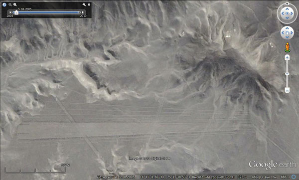
Figure 1. Combination of a wedge with a serpentine.
Judging by the fact that the wedge corresponds to the fan-shaped expansion of the serpentine, it was created on its base. This suggests that the serpentine had a testing or exploratory character. If the water inflow was sufficient and its passing along the knee system was normal, then a part of the serpentine could be cleared from stones and converted into a large field. This is exactly what was done. I call these wedges the second type wedges. Unlike the first type wedges, which we saw in the valleys and which were oriented toward the water flow, these wedges are found on the plains and are set along the slope, i.e., across the direction of the flow.
In Figure 2, we see two more lines going from the elevation to the southeast. Outside of the picture the upper line turns twice by 90º and returns to the beginning as the bottom line. This loop of the serpentine was laid, apparently, to explore the southeast direction. Its water was directed into a new wedge.
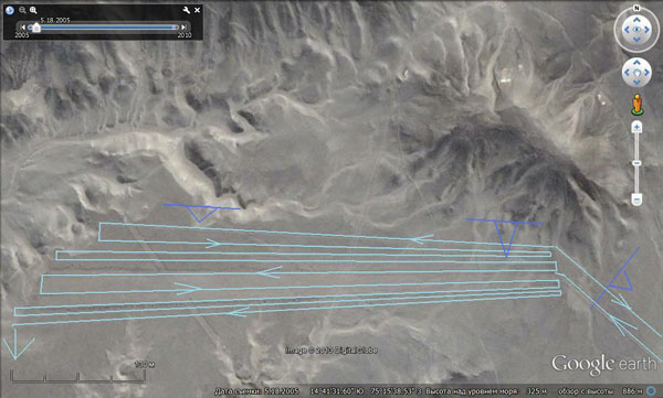
Figure 2. A chart. Blue colour indicates the direction of the inclination of the slopes. Blue colour indicates a serpentine and the direction of the movement of water along it.
A secant band in the left half of the picture has a more ancient origin, as it is cut by the serpentine lines. Besides, its greater length may indicate that it was made when the surface was smooth and not deformed.
Besides, note the lack of rain washouts near the serpentine − the plain is virtually untouched. Note also the differences in the tightness of flows on the slopes of the hill and on the surfaces that are remote from it. This has to do with the issue of showers and groundwater outflow.
The mechanism shown in Figure 3 worked in a similar way. This type of geoglyphs, that resemble an airplane runway, mislead the fans of alien intervention. The main wedge here is very similar to a runway itself, while the rest of the serpentine resembles a steering track.
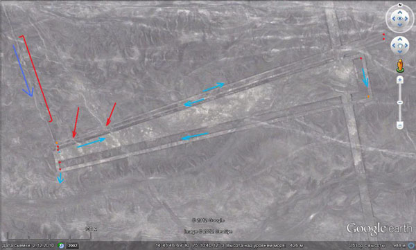
Figure 3. Spots of washouts are indicated by red arrows. Blue arrows show the water flow direction.
Water arrived here along the ditch shown in the upper left corner (a blue arrow) and flew into the serpentine. Its movement is indicated by a blue arrow. The angles of rotation, as in the previous case, are right, which means that the water flow velocity and its volume were not significant. All places of bending are marked by heaps of stones. In the past, they served as orienting point according to which the entire construction was marked out. That is why the lines are straight. The drainage of excess water took place out of the lower-left corner.
Fanlike extension of the right part of the structure was caused, most likely, by the desire to keep the ditch horizontal under the conditions of the declining angle of sloping from this flank (NB: the sloping, naturally, is perpendicular to the striking of the band).
An inlet ditch has traces of erosion. This suggests that at some point it was overflowing with water, which eroded not only the serpentine, but the framing of the wedge as well. However, that happened during the end of its use.
Figure 4 shows a perspective view of another combination of a serpentine and a wedge.
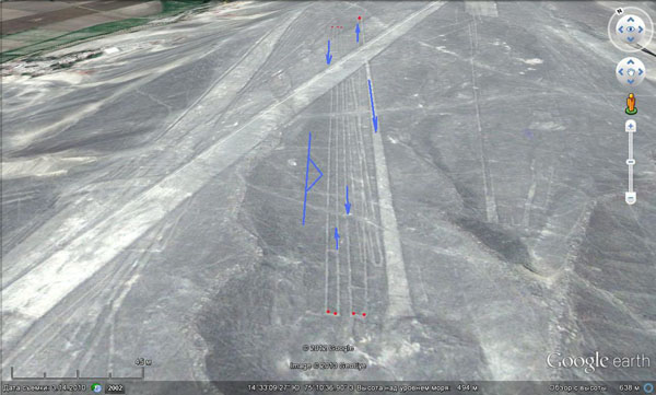
Figure 4. Arrows indicate the direction of water movement. Red dots indicate the heaps of stones at the turns. Near the wedge, one can see a fragment of a more ancient serpentine. The sloping in the past was to the east, nowadays it is at the viewer as well.
Below I am listing a series of wedges of the first type. One can see the traces of ditches along their axis. Approximate coordinates of their centres are presented in the table.
The table of the approximate coordinates of the centres (Figure 5-12).
№ of the figure |
Degrees South Latitude |
Minutes |
Seconds |
Degrees West Longitude |
Minutes |
Seconds |
13 |
14 |
43 |
08,53 |
75 |
11 |
09,02 |
14 |
14 |
40 |
59,96 |
75 |
06 |
25,60 |
15 |
14 |
49 |
14,75 |
75 |
00 |
16,28 |
16 |
14 |
46 |
07,47 |
75 |
01 |
54,07 |
17 |
14 |
48 |
23,12 |
75 |
01 |
20,62 |
18 |
14 |
47 |
51,38 |
75 |
18 |
51,69 |
19 |
14 |
46 |
57,71 |
75 |
10 |
54,34 |
20 |
14 |
46 |
39,41 |
75 |
10 |
55,33 |

Figure 5 |
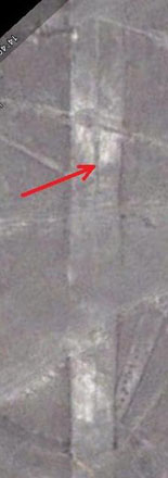
Figure 6 |
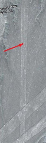
Figure 7 |
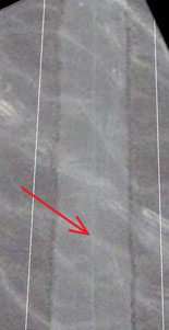
Figure 8 |
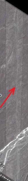
Figure 9 |
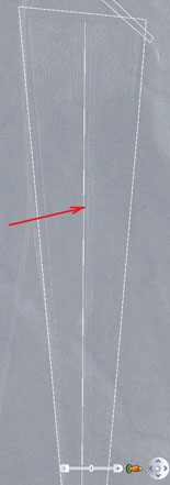
Figure 10 |
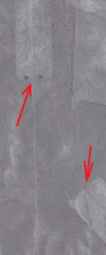
Figure 11 |
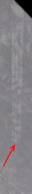
Figure 12 |
All figures № 5-12 are from GE.
In some of the pictures, one can also see heaps of stones in the tops of the wedges.
The ditches are not always visible afield not only because they have flat profile and are difficult to see without stone framing. Often they are ruined by cars tracks − bands and wedges in Nazca were often used as roads prior to the organization of the Reserve in the desert. Understanding that many of these large wedges have axial ditches will help us to solve another odd combination that confused many researchers.
In Figure 13-17 we can see how wedges form something like garlands. From the base of one wedge another one extends, and sometimes even the third one follows. The first wedge is the largest, the second one is much smaller, and the third one is very small. It is never the other way around; a large wedge was never built on a small one.
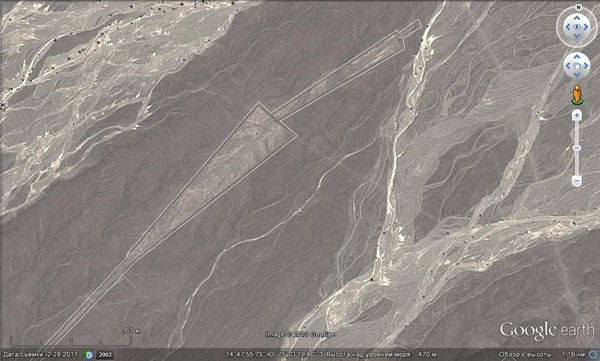
Figure 13. Garland made of 3 wedges. View from space (GE).
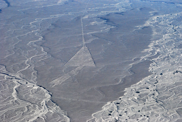
Figure 14. The same garland, a perspective view from an airplane. A central ditch is seen here quite well. It is also seen that later washouts tend to be closer towards the sides of the wedge, where, presumably, there were ditches as well. (Photo from Panoramio № 45868061).
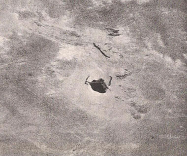
Figure 15. GE.
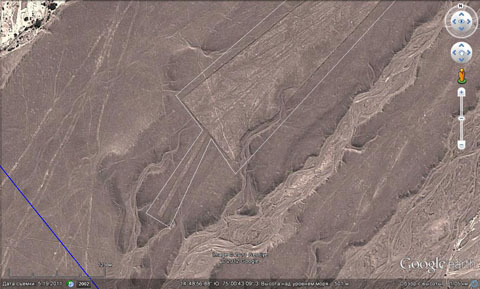
Figure 16. Here, too, one can clearly see an axial ditch. Please note how small a new wedge is (GE).
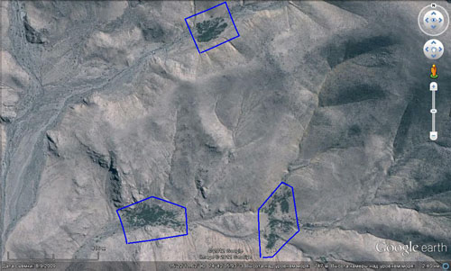
Figure 17. (GE).
This feature has prompted the idea that smaller wedges, which were built on bigger ones, were fed by the excesses of water, that was not used in the biggest wedge. It was the easiest to take the excess water from the central ditch. Therefore, the point of attachment of additional wedges was usually located in the centre of the foundation. Moreover, this point is often marked with a pile of stones. There is always one pile, because it was intended to cover only one ditch instead of three ditches like at the top of the wedge.
It turned out that this way people increased irrigated area using the familiar method. A central ditch was used as a new source from which, taking into account the direction of the flow, a new ditch was dug. Then, on the basis of a new ditch a new wedge was made, the length of which had to keep with the quantity of water.
I think that these were some rapidly created structures made in response to a currently abnormal situation (there was more water coming to the wedge than usual). Therefore, they often had poorer quality than a parent wedge.
There are traces of the reverse process as well − reducing the field area by moving of a lower boundary of the wedge up. They are presented in Figure 17.
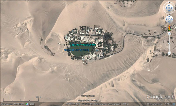
Figure 18. Drawing closer of the lower boundary of the wedges.
Figure 19 shows a diagram of the wedge of the first type. Water comes from the top and diverges along the ditches, around which wet zones are being formed. These ditches were to be located in a way to ensure the absence of dry places. Water should reach the lower boundary of the wedge along side ditches. That is the whole algorithm of its work. Itdetermines the divergence angle of the sides. If they diverge too widely, there will be dry spots between the ditches and water will not be able to reach the bottom. If they are too close, i.e., the sides of the wedge are parallel, there will be enough moisture, but the area of the field will be too small.
Very likely, the spots of wet sand were the original example to follow. These spots were developing down the hill after the source of water would start functioning. Making a ditch across such wet spot people could deliver water to more remote areas and thus increased the acreage. Making fields on an incline surface it was easier to avoid water logging of the soil, that would be destructive to many plants.
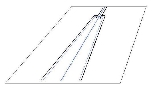
Figure 19. Diagram of the wedge functioning. Blue lines mark ditches.
Interestingly, Figure 20 shows another combination that allows us to trace the evolution of the lines in time.
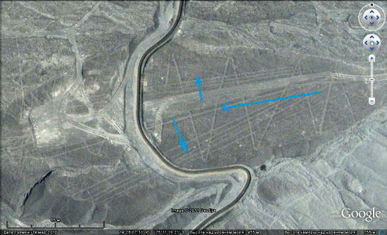
Figure 20. Evolution of a zigzag along the axis of uplifting into an axial wedge and further on into zigzags on the sides of uplift. (NB: In the centre of the picture the wedge is cut not by a road but by a concrete water channel, that transports water by natural flow from Rio Grande to the valley of Palpa for a distance of about 30 km).
Figure 21a, 21b, and 21c illustrate the steps of this evolution (we are looking from above, from west to east).
The earliest figure is a zigzag (21a). It was made when the elevation just became apparent and presented a smooth flat surface surrounded by barely noticeable depressions. Then, in the process of the development of a crosscut relief on this elevation the zigzag blocked the water flow. Then a wedge (21b) was made along the uplift axis, along the watershed. The wedge, like the zigzag, worked due to the general sloping of the area from east to west, which ensured the flow of water in the same direction. Further growth of the elevation led to the emergence and expansion of the slopes. Now, the water coming from the east tended to drain from the wedge to the right or left. This was used by people. They created serpentines on both slopes expanding the area of irrigation (21c).
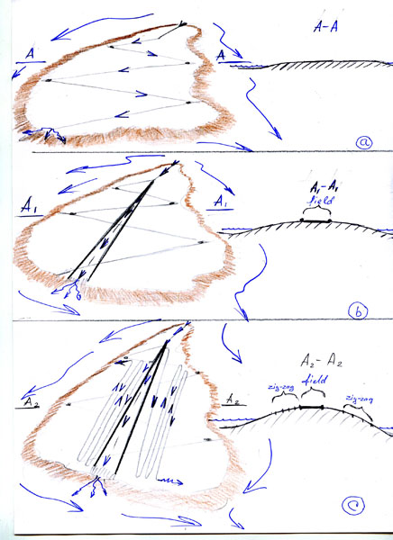
Figure 21. The diagram of the evolution of the geoglyphs in Figures a, b, c. Blue arrows indicate the direction of water flow.
The wedge on the slope of the left side of the valley near the town of Palpa originated in about the same way.
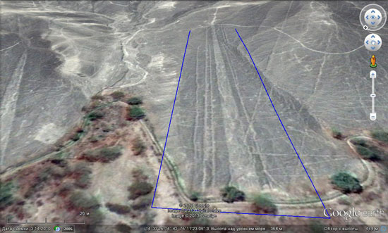
Figure 22. Left banks of the Viscas and Palpa valleys.
Figure 23 shows an intricate combination of several serpentines, wedges and rectangular spirals. It is located within the city on the right side of the Palpa valley. The slope is going down from north to south.
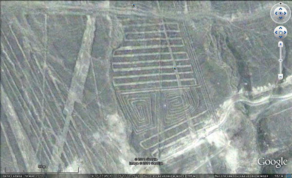
Figure 23. So called sundial (Solar relox).
Initially, this area, most likely, was almost horizontal. Perhaps, only a part with a serpentine was slightly sloping to the south. Water from the slope first flowed through the upper serpentine, then, it filled spirals, flew out of them, and finally through the lower serpentine went into a depression, which was subsequently transformed into a ravine. We can see it in the background of Figure 24. As in all previous cases, spirals here are double. We have already discussed the reasons of such phenomenon.
With further development of the relief the horizontal platform deformed, its slope changed and became greater, the serpentine and spirals stopped functioning. Then people made a wedge and another serpentine to the top of them, which supplied with water from the depression located in the east.
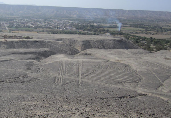
Figure 24. «Solar reloj» view from the observation platform.
This irrigation system could allow having here a small (1 hectare) field. The object that modern guides present as a sundial, is likely the consequence of the isometricity and roundness of the structure (similar to a dial piece!!!) and its systemic compartmentalization by geoglyphs (time intervals). Besides, the “product” under this guise is selling better. It is not by accident that one has to pay to go to a viewing platform here. However, it would be interesting to hear how some adepts of this version explain the mechanism of functioning of this “clock”.
Here are some more serpentines both on the territory of the Nazca desert and in its surroundings.
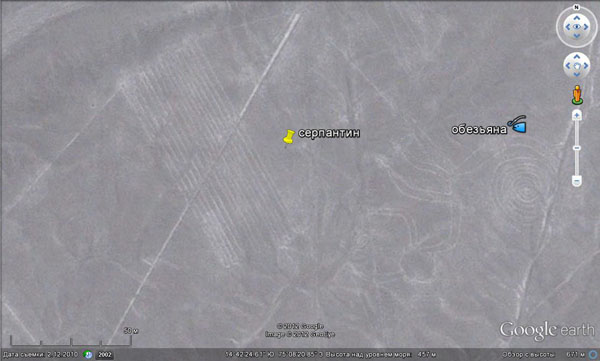
Figure 25. Serpentine near the picture of Monkey in the Nazca desert.
Figure 25 shows a tight serpentine located now on a barely noticeable hill surrounded by dry riverbeds. During the time of water abundance there used to be a small plain here.
Water intake took place by the means of the ditch located in the centre of the northern boundary of the picture.
There was the image of a monkey on a nearby similar elevation to the right.
At higher magnification, one can see that the spots where the lines turn are marked by dark points, that is, the piles of stones. It is a common practice caused, apparently, by the convenience of “aiming” of lines in the process of marking. Recently I heard that the exact same guidelines (the piles of stones) were used while laying the Imperial Inca road across the Andes stretching for 5,000 km.
Figure 26 presents a serpentine differing from the previous ones by its freer form. It is located in the north of Nazca in the area of the maximum density of geoglyphs. The presence of a riverbed clarifies the situation. This serpentine is located on the slopes of a small depression, in which a creek appeared. The lines-ditches that crossed the creek from one side to another had a certain angle for the passage of water flowing from somewhere above. This allowed irrigating the occupied space evenly. Subsequent developments of the relief led to the formation of a deeper depression, into which waters from multiple sources streamed. These sources were widely developed here (white spots and dots). The new creek cut through the established system of lines, thereby stopping its work.
Here one can also see some strange drawings or signs that were made, like serpentines, in a technique of one line that does not cross itself.
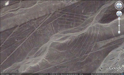
Figure 26. Serpentine in the emerging depression that later accommodated a stream. The northern corner of Nazca, the most intensely filled with geoglyphs.
Let us now consider a few cases that also demonstrate the functioning of wedges and serpentines.
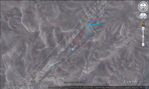
Figure 27. An accident. Blue arrows show the place of the breakout and the direction of the water flow.
Figure 27 presents fixing of an emergency situation caused by breakout of the band-limiting roll and pouring of water outside of the band. Figure 28 presents a panoramic view of the site. In place of the breakout one can even see light washouts on the surface of the plain. The situation was serious enough, because no water would get to the wedge, the beginning of which we see in the lower left corner. Apparently, it was impossible to fix it by simple rebuilding of the wall because the breakout was associated with a change of the geometry of the surface that was the result of the beginning of the restructuring. Then it was decided to lay a bypass ditch to the wedge, and water was directed to the ditch. To control incoming water two piles of stones were made at the place of water intake. Thus, the functioning of the wedge was possibly restored.
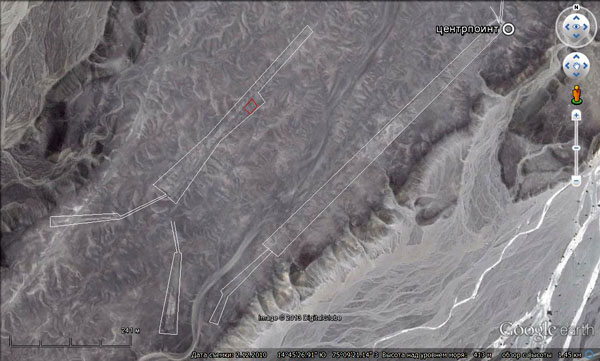
Figure 28. A general view of the site. Red square indicates the place of the accident.
NB: the surface surrounding geoglyphs and reminding frost flowers on the glass is nothing else but the deformation of the surface of the plain, manifested in the formation of many small positive and negative structures. The latter sometimes became the beds of watercourses.
Another case is presented by a well-known structure located to the south of Cahuachi. That is how it is presented in the article by I.A. Alekseev “Nazca geoglyphs”" posted on the website "Labs of alternative history” (http://www.lah.ru/text/alekseev/nazka2.htm).
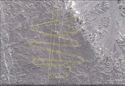
Figure 29. Geoglyph called “Snake” on a plateau 2 km to the south of Cahuachi (From the article by I. Alekseev ric098).
Such configuration of a geoglyph seems not to fit into the proposed scheme of their work. A serpentine should not cut itself, if it does it has no use.
Everything becomes clear, if you look closely at the place where both the serpentine and the wedge start. In this picture they are connected into a single structure.
In fact, they are two different geoglyphs originating from one hill.
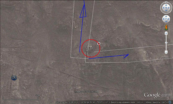
Figure 30. Centrpoint “Snakes”. A wedge goes up, a serpentine goes right. Circle indicates the hill supplying geoglyphs with water. Its top is marked whether with a pile of rocks, or with a well. The serpentine was being created when the territory was almost perfectly flat and had a slight slope to the north. In this direction, as the water is being used up the band of the serpentine becomes narrower, as if forming a tail of a snake. The wedge was made after the serpentine stopped functioning due to the deformation of the surface. I.e., everything was as usual.
Nowadays this plain, like the whole Nazca, is slight sloping to the west, due to the growth of the Andes on the east, and is complicated by numerous smaller positive and negative structures. Today, even if there were water, the topography would not let revive any of the geoglyphs.
This example shows that when studying each geoglyphs one should be very attentive to all detail.
Figure 31 presents a wedge with tributaries. Things that for some reason were not found in Nazca happened to exist 450 km north of Lima in one of the valleys going into the ocean.
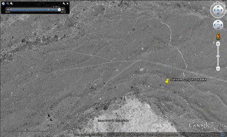
Figure 31. Wedge with tributaries.
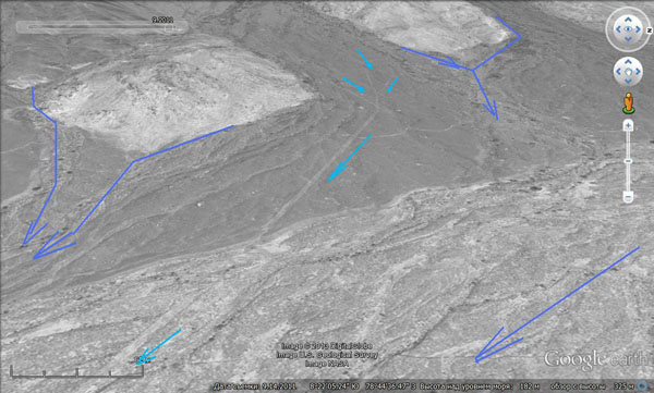
Figure 32. Perspective view of a wedge with tributaries. Blue arrows show the position of modern river beds. Blue ones indicate water flow along the wedge.
As seen in Figure 32, geoglyph occupies a watershed between two depressions on the left and right, although it is confined to the valley. The wedge is expanding down in the direction of the drain and there are some light spots here as well, indicating the presence of water sources. In this place it is not one geoglyph, there are parallel wedges to the right (to the north).
Wedges similar to those in Nazca are found in other places along the coast of Peru, but everywhere they are sporadic, not large in size, and not characterized by perfect geometry. Besides, they are usually confined to the river valleys.
This may tell us that there were not many places where the usage of similar irrigation systems was justified. However, the very attempt to use such a relatively inefficient irrigation systems may indicate that the lower reaches of rivers, where now the main agricultural lands are, were not drained or developed then. Almost all wedges considered earlier had complied to a general rule − they had expanded downwards in the direction of water flow. The line entering them started even higher. Indeed, it is generally typical of most geoglyphs. Still, there are some exceptions. One of them is shown in Figure 33.
Here the line starts as usual, under the slope of a small elevation and goes northeast ending as a typical wedge. The only problem is that instead of going down it rises to it. The height at its beginning is 617 m, but at the base of the wedge it is about 690 m. The violation of the general rule took place later due to the growth of the Andes, when the territory acquired an opposite direction of sloping compared to the original one. This scheme is shown in Figure 34. Once I wrote that larger structures develop after the smaller ones.
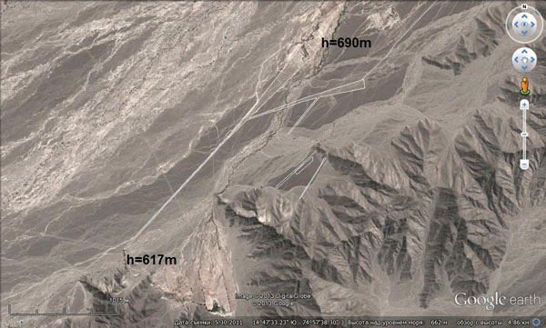
Figure 33. “Reverse wedge”.
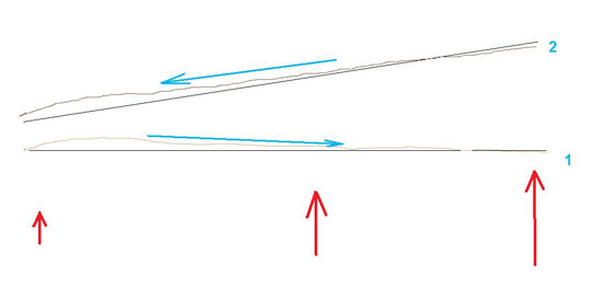
Figure 34. A diagram showing the change of the surface sloping in the process of the reorganization of the relief.
1 − initial position, the drain is determined by a small elevation in the left part.
2 − the territory was subjected to a larger uplift which raised it to another altitude level and changed the direction of the flow to the opposite while preserving some surface features. Hence the violation of the general rule.
This had happened in all cases where we observed the violation of the rule. More often it is observed on the plain. It is due to some very small angles of surface sloping, that allowed changing them easily to the opposite due to tectonic processes. That is why we were fortunate to begin studying geoglyphs in mountainous areas. In the mountains, that is, in “weak” areas subjected to compression, all tectonic trends are seen more clearly. Positive and negative forms are manifested with much greater contrast than on the plains. Therefore, subsequent tectonic processes in mountainous areas usually only reinforce existing tendencies, but almost never smooth them.
If we, like Maria Reiche, concentrated on the desert, although there is an abundance of geoglyphs there, we would have never grasped their nature. The angle of its sloping was changing with time and it resulted in a change in the direction of water flow and led to creation of hundreds of lines and wedges overlapping each other. Their position fixed a tectonic situation for some short time. Ancient inhabitants of Nazca were forced to constantly monitor and respond to the challenges of nature. Perhaps, it was this situation that formed in this part of the world a nation with extremely rich and unique material culture.
Since we raised the issue of tectonic changes in the earth surface I will bring some of the most striking examples of this phenomenon using geoglyphs.
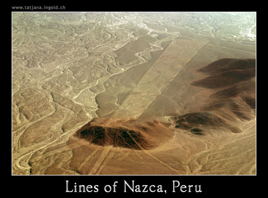
Figure 35. A small hill that grew up under the wedge. Photos from Panoramio № 1286071.
The accuracy in laying lines oner such hills (Figure 35) makes modern researchers to stand in awe and forces them to think seriously about the alien origins of the lines’ creators. Before the formation of the hill this place had a barely noticeable elevation covered with heaps of rubble, from which moisture oozed. Actually, the wedges were laid on the surface with a barely noticeable sloping in different directions. It was one of the smaller Centrs.
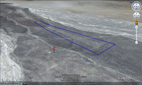
Figure 36. Hill formed under the sharp corner of the wedge.
In Figure 36, one can see how the hill that was formed raised a thin part of the wedge and changed its vertical profile.
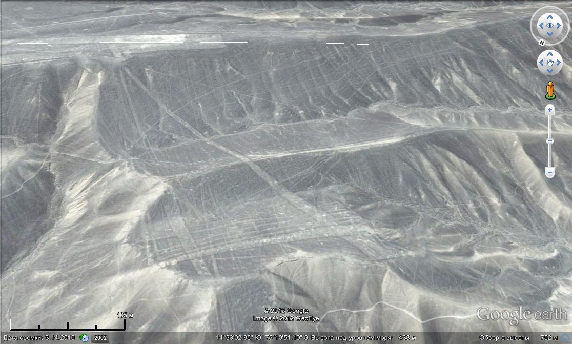
Figure 37. Wedge begins at the top of the plateau and crosses two valley that were formed later.
In Figure 37, one can see how a ridge was formed under the wedge that made water flow impossible. The slope of the ravine, that was formed on the left, partially erased neighboring lines and wedges. However, the ravine itself and its slopes are not erosive, as it is evident by preserved traces of lines here and there, but talus and tectonic. Traces of erosion are visible only in the mainstream, along which the excesses of water used to flow some time after the restructuring forming a thin light band of alluvium represented by washed pebbles.
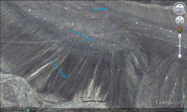
Figure 38. Deformation line due to elevation. Attention: North is in the left. This line stretches from here for 500 m crossing several valleys and peaks.
There are hundreds of smaller examples, some of them we have encountered before.
Geoglyphs can become invaluable to researchers who study the functioning of relief-forming tectonics. Knowing what it was like and what has become out of it makes it easier to understand the mechanism of its functioning. What had to happen to cause such changes in the relief? What kind of forces were behind it? Why it is so and not some other way that mountains react to these forces? And, finally, what is the scale of this process?
| << Previous | Contents | Next >> |


